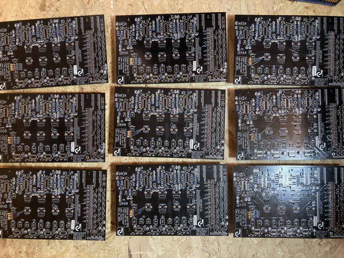
Here it is: the JCQS-440 A.F.V. also known as the Wurlyscope.

QuadraphonicQuad

Help Support QuadraphonicQuad:

This site may earn a commission from merchant affiliate links, including eBay, Amazon, and others.
Oh! The parts are on the wrong side. I thought you just put the solder on the wrong side.
 
Hi all!
Have a look of the cut wires of about 440 LEDs...
IMG_4851.jpeg
 
So that's 880 little wires. Hmmm.... comes in handy for jumpers I guess.
That’s what i taught at first but one of my little screwdriver and the tip of one of my long nose plier are slightly magnetized…
These little :devilish:
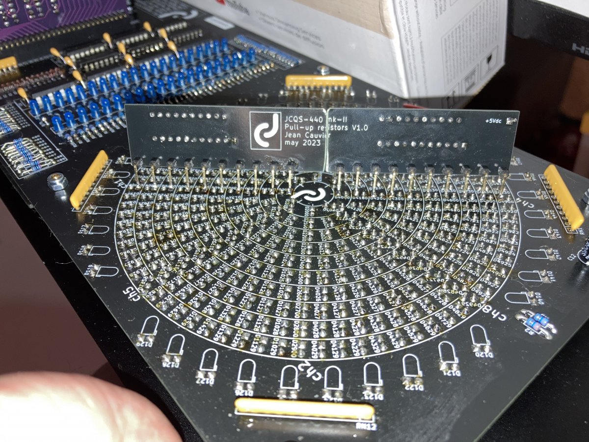
wires are flying all over the place…
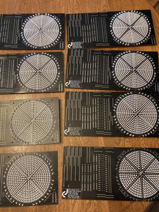
I throw them away almost immediately and keep only few ones.
 
Hi all!
So far i have managed to populate 8 pcb screens with LEDs.
7 mk-II and 1 mk-III. A very time-consuming exercise.
note: the missing diagonal LEDs are those i had to re-order because of the wrong size.:geek:
 

Attachments

  • IMG_4867.jpeg
    IMG_4867.jpeg
    259.8 KB · Views: 20
Hi All!
I did some modifications to the mk-II circuits to protect the LEDs from excessive reverse voltage.
I replaced half the screen driver ics with ones featuring open collector outputs.
To work properly these needs some pull-up resistors. But where to put them?.
To solve the problem, i designed some new pcbs holding 20 x 10k resistors and placed it right over ch 1 & 4 LEDs.
See the results in these pictures.
note: On the prototype i split the board in two because i taught i had made a measurement mistake. Finally their size is perfect.
I am now working very hard to complete everything. By the weekend, if the weather is good, i will begin the cabinets,:SB
 

Attachments

  • IMG_5030.jpeg
    IMG_5030.jpeg
    296.2 KB · Views: 34
  • IMG_5032.jpeg
    IMG_5032.jpeg
    391.2 KB · Views: 33
Hi All!
I did some modifications to the mk-II circuits to protect the LEDs from excessive reverse voltage.
I replaced half the screen driver ics with ones featuring open collector outputs.
Do you have the same problem with the mk-III?
 
Do you have the same problem with the mk-III?
No in the mk-III reverse voltage is about 3 volts which is quite safe.
Now it's also about 3 volts in the mk-II. (it was 5 volts before)
The pull-up resistors on ch 1 & 4 are there to insure proper operating of the ch. 7 & 8.
I know it seems illogical but it the logic circuitry, it is! :cool:
 
Good news!
i finished LED soldering!
Well almost, still waiting for the rectangular ones but it's not a big deal now.
Il will finish the rest of the circuitry and the amplifier modules in the next few days
and i hope i'll have some good weather next weekend to make the cabinets as i have
to go outside to make all the wood working.
Don't despair! I'm getting there soon!
:cool:
Can I make mine in a rare East African Kilimanjaro Organic Zebra Rump finish with Plutonium filigrees on the power button ( so it glows in the dark )?

I was just thinking, since you got so good at soldering (!) can I have mine with alternating colors in the main vector LED lines (you know, like blue, white, blue, white...).

Hey! Don't be throwing things at me! That almost hit me. :)

800 cut wires from LEDs just stuck to the books behind me.....
 
Hi all!
My little friday report...
The mk-II control boards and the mk-III main boards.
All small precision-matched resistors are soldered, the rest of the parts will go swiftly.
note: the mk-III without LEDs are not sold yet. I will put them aside for now.
Nice weekend! :cool:
 

Attachments

  • IMG_5034.jpeg
    IMG_5034.jpeg
    345.8 KB · Views: 20
  • IMG_5035.jpeg
    IMG_5035.jpeg
    430.5 KB · Views: 18
  • IMG_5036.jpeg
    IMG_5036.jpeg
    371.9 KB · Views: 19
  • IMG_5037.jpeg
    IMG_5037.jpeg
    440.2 KB · Views: 20
  • IMG_5038.jpeg
    IMG_5038.jpeg
    340.7 KB · Views: 20
Floyd on OG Wurlyscope, Sansui QSD-2 Synth. Mode.
You might have to watch an ad to pay for royalties of Pink Floyd copyright :)


In the LED field, the 4 diagonal "channel beams" (that I guess are the center of that channel's representation), do they get the same input signal as the field LEDs and just look different due to their physical setup differences?
 
In the LED field, the 4 diagonal "channel beams" (that I guess are the center of that channel's representation), do they get the same input signal as the field LEDs and just look different due to their physical setup differences?
This a an mk-I unit it doesn’t have a center channel, it is a quad unit.
The diagonals are Front-Left, Front-Right, Rear-Left & Rear-Right.
The fields in blue represent the wave form spatial interactions.:cool:
 
In the LED field, the 4 diagonal "channel beams" (that I guess are the center of that channel's representation), do they get the same input signal as the field LEDs and just look different due to their physical setup differences?
The camera makes it look brighter than it really is, the 4 cardinal channels are actually white LEDs and the blue LED fields represent relationships between adjacent channels. If there is sound only one channel(like a test tone), only the white LEDs will light, as soon as there are simultaneous sounds in adjacent channels, the blue LEDs will also light, that is where the magic is happening.
 
Back
Top